The firmware for the ESP8266 microcontroller was developed in the C/C++ programming language using the Arduino Framework. The code was programmed on the PlatformIO IDE for the Microsoft Visual Studio Code editor (VSCode). For more details on programming the ESP8266 mounted on an ESP-01 module, its pinout, and how to connect the module to the Arduino MEGA, please refer to The ESP-01 Module Programming Guide.
The current version of the ESP8266’s firmware has three main functionalities, which are:
- Establishing a Wi-Fi connection to the Internet for the Arduino MEGA microcontroller or another master connected to the serial port.
- Sending the data collected by the master microcontroller to the RENOVAr web server as HTTP posts.
- Getting the time from an NTP Server.
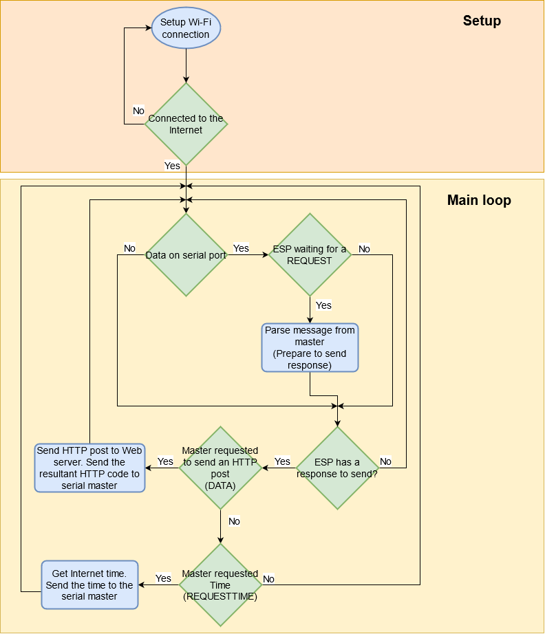
Figure 1 shows a flowchart of the code programmed for the ESP8266. Firstly, the program establishes a connection to the Internet through a Wi-Fi network. Once the connection has been established, the program listens to the serial port waiting for a request from the master microcontroller connected to the serial port. For each request received from the serial master, the ESP8266 executes a particular operation and sends its result back to the master. The messages interchanged between the ESP8266 and the master are strings in JSON format. For the current version of the firmware, the master can make two kinds of requests. It can request to send an HTTP post or it can request the time.
Setup and Wi-Fi connection
As shown in the flowchart of Figure 1, the first actions that the program executes are those related to establishing a Wi-Fi connection to the Internet and serial communication. Those are accomplished in the functionsetup() as shown in the code below.
void setup()
{
  Serial.begin(9600UL);
  Serial.print(F("+STARTESP;"));

  setup_wifi_connection<NUM_WIFIS>(wifiCreds);

  espHTTP.set_available(true);
  espSerial.set_status(WT_REQUEST);
  Serial.print(F("+ESPREADY;"));
}
Firstly, the program starts the ESP8266 Serial port at a baud rate of 9600 bauds and prints the message ‘+STARTESP’, indicating to the master that the ESP has started. The function setup_wifi_connection establishes a connection to a Wi-Fi network that has been previously stored in wifiCreds. Finally, once a connection has been established, the object espHTTP is made available for executing HTTP operations, the state of the object espSerial is declared as WT_REQUEST, and the message ‘+ESPREADY’ is printed, indicating that the ESP8266 is waiting for a request from the serial master. Table 1 describes the objects, constants, and functions that are used in this part of the code.
Table 1. Objects, constants, and functions used in the setup function
| Name | Description |
NUM_WIFIS | This constant defines the number of Wi-Fi networks that the ESP8266 will try to establish a connection with. It must be declared before declaring the wifiCreds object and before invoking the function setup_wifi_connection().#define NUM_WIFIS /*The number of Wi-Fi networks*/ |
WiFiCredentials wifiCreds[] | This variable is an array of objects of the type WiFiCredentials. This array stores the SSID, password, and username (only for WPA3 ENTERPRISE networks) of the network. The array wifiCreds must be declared before the setup() function, as follows:/*Declare the credentials of a WPA3 Enterprise Network*/const WiFiCredentials CRED_1("ssid1", "password1", ENTERPRISE, "username1");/*Declare the credentials of WPA3 Personal Networks*/const WiFiCredentials CRED_2("ssid2", "password2", PERSONAL);/*Declare the wifiCreds array*/const WiFiCredentials wifiCreds[NUM_WIFIS] = { CRED_1, CRED_2, CRED_3 };For more information on the type WiFiCredentials refer to The IoT Package Documentation. |
setup_wifi_connection<NUM_WIFIS>(wifiCreds) | This function establishes a connection to a Wi-Fi network. It is defined as a template that receives the number of Wi-Fi networks registered in wifiCreds. For more details on this function please refer to The IoT Package Documentation. |
espHTTP | This variable is an object of the class, defined in the file esp-iot.h. The purpose of this object to encapsulate the functionalities related to the HTTP operations. For more information please refer to The IoT Package Documentation. |
espSerial | This variable is an object of the classESPSerialHandler, defined in the file esp-serial-iot.h. The purpose of this object to encapsulate the functionalities related to the serial communication between the ESP8266 and the master. Depending on the state of this object, the ESP8266 may read a serial message from the master, or execute a particular operation and send its result back to the master. For the current version of the firmware, we have implemented two states: WT_REQUEST: Indicates that the ESP8266 hasn’t received any new request from the master and is expecting one.WT_RESPONSE: Indicates that the ESP8266 has received any new request from the master and is waiting to respond.For more information please refer to The IoT Package Documentation. |
Serial | This is an object of the Arduino framework for modeling serial communication. For more information, please refer to the Arduino Reference. |
The main loop
The main loop is executed in the function loop()of the Arduino framework, as shown in the code below. This function is responsible for monitoring the ESP8266’s serial port and attending to the requests from the master, as was already illustrated in Figure 1.
void loop()
{
  static CommandTypes _cmdType = ERROR;

  if(Serial.available())
  {
    String serial_Str = Serial.readStringUntil(';');
    if(espSerial.get_status() == WT_REQUEST)  _cmdType = espSerial.parse(serial_Str);
    Serial.flush();
  }
  if(espSerial.get_status() == WT_RESPONSE)
  {
    espSerial.set_status(WT_REQUEST);
    switch (_cmdType)
    {
      case DATA:
      {
        static uint8_t _numberOfPostTries = 0;
        #define MAX_NUM_TRIES 3
        int code = espHTTP.post(HOST, PORT, URL, espSerial.get_data());

        if(code <= 0 && WiFi.status() != WL_CONNECTED)
        {
          setup_wifi_connection<NUM_WIFIS>(wifiCreds);
          if(++_numberOfPostTries >= MAX_NUM_TRIES-1) ESP.restart();
        }
        else  espSerial.send_http_code(code, Serial);
        break;
      }

      case REQUESTTIME:
      {
        static uint8_t _numberOfTries = 0;
        #define MAX_NUM_TRIES 3
        time_t t = get_time(TIMEZONE_SEC,DAYLIGTHOFFSET_SEC);
        if(!t && WiFi.status() != WL_CONNECTED)
        {
          setup_wifi_connection<NUM_WIFIS>(wifiCreds);
          if(++_numberOfTries >= MAX_NUM_TRIES-1) ESP.restart();
        }
        else  espSerial.send_time(t, Serial);
        break;
      }

      default:
      {
        break;
      }
    }
  }
}
Checking the requests from the master
Any time there is data on the serial port and the status of the espSerial object program is “waiting for a request” (WT_REQUEST), the espSerial will parse that data in order to determine what kind of request the master has sent. This is done in the first if of the loop() function, as shown in the code below.
if(Serial.available())
{
  String serial_Str = Serial.readStringUntil(';');
  if(espSerial.get_status() == WT_REQUEST)  _cmdType = espSerial.parse(serial_Str);
  Serial.flush();
}
Once the master’s message has been parsed, the espSerial will set its state to “waiting to respond” (WT_RESPONSE), which indicates that there is an operation to be made and a response to be sent back to the master (this is done internally in the parse function). If the status of espSerial is WT_RESPONSE, the program will perform a switch for determining which operation the microcontroller should execute next (see Figure 1). That selection will depend on the type of request, or command, sent by the master, which has been previously stored in the variable _cmdType as a result of the parse function executed by espSerial. Figure 2 shows this process.
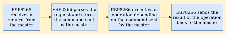
For the current version of the firmware, the ESP8266 accepts two kinds of requests or commands from the master: (1) a request to send an HTTP post or (2) a request for the time. The structure of a request message is shown in the JSON below. Once the espSerial object has processed the message from the master, it stores the type of request into the _cmdType variable. This variable is an enumeration defined as CommandTypes and, for the current version, can contain the values ERROR, DATA and REQUESTTIME, see Table 2.
The format of the JSON string interchanged between the ESP8266 and the master
{
  'type': // The type of the request. Could be 1 (DATA) or 2 (REQUESTTIME)
  'body': // The body of the request. Only used when the master is sending data (DATA)
}
Table 2. Types of requests represented in the type CommandTypes
CommandTypes | Value | Description | Response to master |
ERROR | 0 | This command indicates that an error has occurred in the communication from the master to the ESP8266. Normally used from ESP8266 to master. | It is the response in the case of communication error |
DATA | 1 | This command indicates that the master has sent the data for an HTTP post, and is waiting for the HTTP code returned from the Web server as a response to the post. | The HTTP code returned by the Web server after posting |
REQUESTTIME | 2 | This command indicates that the master is requesting the time from an NTP Server. | The timestamp obtained by the NTP Server. |
The DATA command: making an HTTP post to the web server

The code executed when the master requests to send an HTTP post is shown below. The espHTTP object makes a post to a web server identified by a HOST, a PORT, and a specific URL. The data sent in the POST is the one previously sent by the master, which can be accessed by the method get_data()of espSerial. The code returned from that operation is sent as a response to the master. If the code is negative and the ESP8266 is not connected to the Wi-Fi network, the program will try to reconnect to the network and re-post the data for a maximum of three tries. On the other hand, if the code is negative but the ESP8266 is connected to a Wi-Fi network, the program will try to re-post indefinitely until the master sends a new request. Figure 3 shows a flowchart that represents this process. For more information about the objects ESP and WiFi used in this code please refer to the ESP8266 Arduino Core’s Documentation. For more details on the other functions and objects used in this code refer to The IoT Package Documentation.
case DATA:
{
  static uint8_t _numberOfPostTries = 0;
  #define MAX_NUM_TRIES 3
  int code = espHTTP.post(HOST, PORT, URL, espSerial.get_data());

  if(code <= 0 && WiFi.status() != WL_CONNECTED)
  {
    setup_wifi_connection<NUM_WIFIS>(wifiCreds);
    if(++_numberOfPostTries >= MAX_NUM_TRIES-1) ESP.restart();
  }
  else  espSerial.send_http_code(code, Serial);
  break;
}
The values of HOST, PORT, and URL are defined in the file iot-generic.h as follows below; they represent the endpoint for posting data to the RENOVAr web server.
#define HOST  F("renovar.lcqar.ufsc.br")
#define PORT  8080UL
#define URL   F("/sample/")
The REQUESTTIME command: getting the time from an NTP server
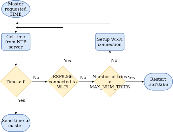
The code executed when the master requests the time is shown below. The function get_time() is defined in the file esp-iot.h for getting the current timestamp from an NTP Server. The timestamp returned from that operation is sent as a response to the master. If the timestamp is zero and the ESP8266 is not connected to the Wi-Fi network, the program will try to reconnect to the network and get the Internet time for a maximum of three tries. On the other hand, if the timestamp is zero but the ESP8266 is connected to a Wi-Fi network, the program will try to get the Internet time indefinitely until the master sends a new request. Figure 4 shows a flowchart that represents this process. For more information about the objects ESP and WiFi used in this code please refer to the ESP8266 Arduino Core’s Documentation. For more details on the other functions and objects used in this code refer to The IoT Package Documentation.
case REQUESTTIME:
{
  static uint8_t _numberOfTries = 0;
  #define MAX_NUM_TRIES 3
  time_t t = get_time(TIMEZONE_SEC,DAYLIGTHOFFSET_SEC);
  if(!t && WiFi.status() != WL_CONNECTED)
  {
    setup_wifi_connection<NUM_WIFIS>(wifiCreds);
    if(++_numberOfTries >= MAX_NUM_TRIES-1) ESP.restart();
  }
  else  espSerial.send_time(t, Serial);
  break;
}
The function get_time() receives the parameters TIMEZONE_SEC and DAYLIGTHOFFSET_SEC, which are defined previously in the main.cpp file. The example below shows how we set these two parameters for our application in Brazil. TIMEZONE_SEC is the timezone where the monitor will be installed, converted into seconds. DAYLIGTHOFFSET_SEC sets the offset, in seconds, for daylight saving time.
#define TIMEZONE_SEC        -3*3600
#define DAYLIGTHOFFSET_SEC  0*3600