The firmware for the ESP8266 microcontroller was developed in the C/C++ programming language using the Arduino Framework. The code was programmed on the PlatformIO IDE for the Microsoft Visual Studio Code editor (VSCode). A description of the main features of the firmware developed is available at The ESP8266 Firmware. For more details on configuring the development environment refer to Setting up the Development Environment. In this guide, we will describe the procedure for programming the firmware into the ESP8266 microcontroller.
Creating a project for ESP8266 using VSCode and PlatformIO
The process for creating a new project for an ESP82266 microcontroller using VSCode and PlatformIO is pretty simple and straightforward. This is only described in case you would like to start your own project from scratch. The project for the firmware we developed is already configured and there’s no need to follow these steps. In case you’re using our code refer to Setting up the Development Environment if you haven’t configured the development environment and go directly to Uploading your Code to the ESP.
- Within VSCode go to PIO Home and select New Project

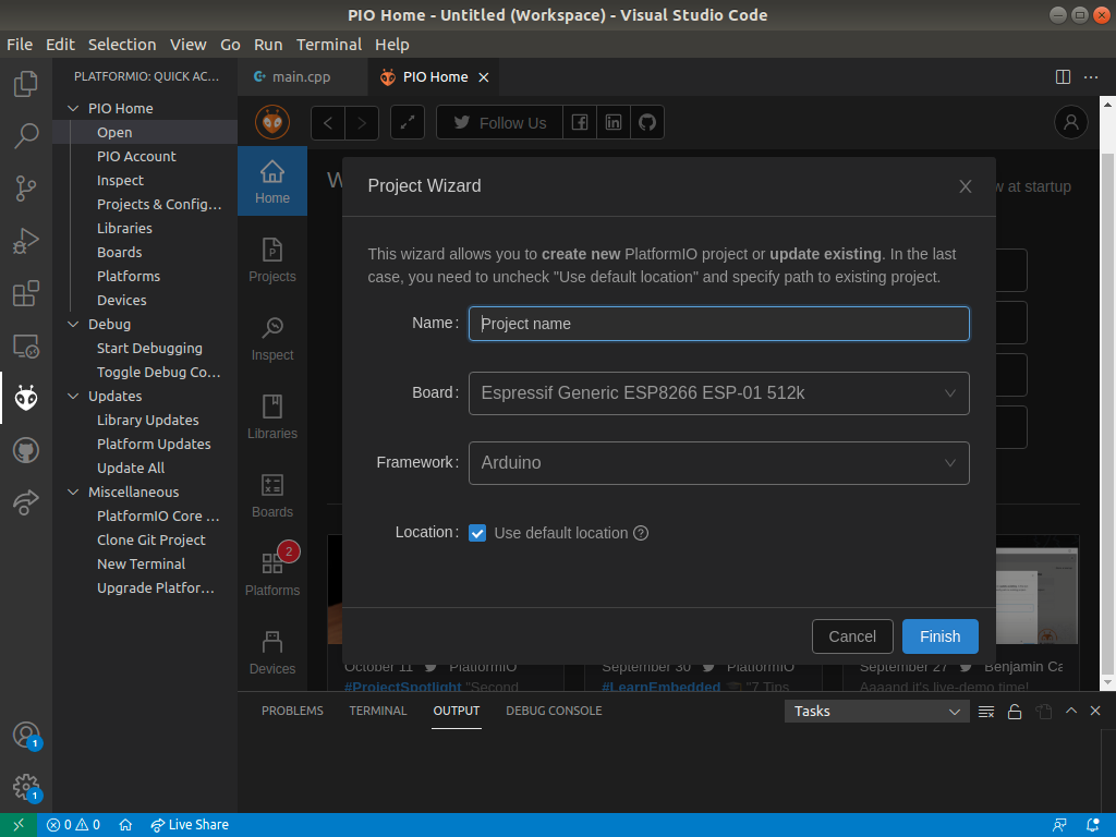
2. In the Project Wizard choose a name for your project, select your board and the Arduino framework. In case you are using an ESP8266 on an ESP-01 board with 512 kB of Flash memory (like in our project), your Project Wizard should look something like Figure 2. In other cases select your board accordingly.
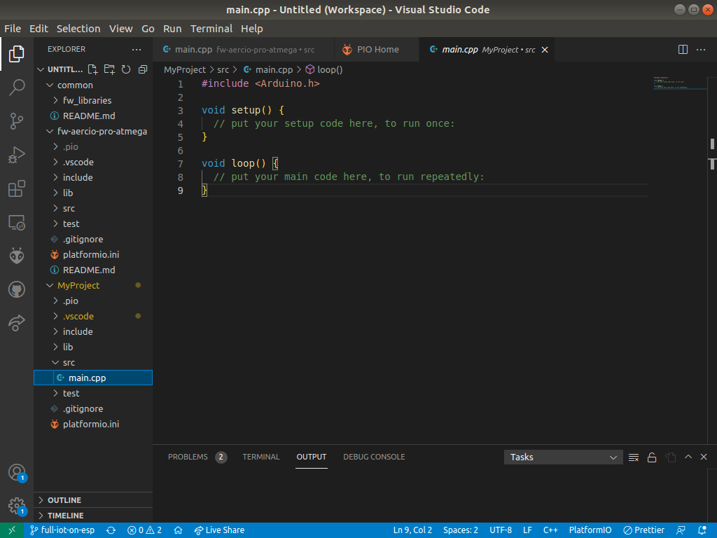
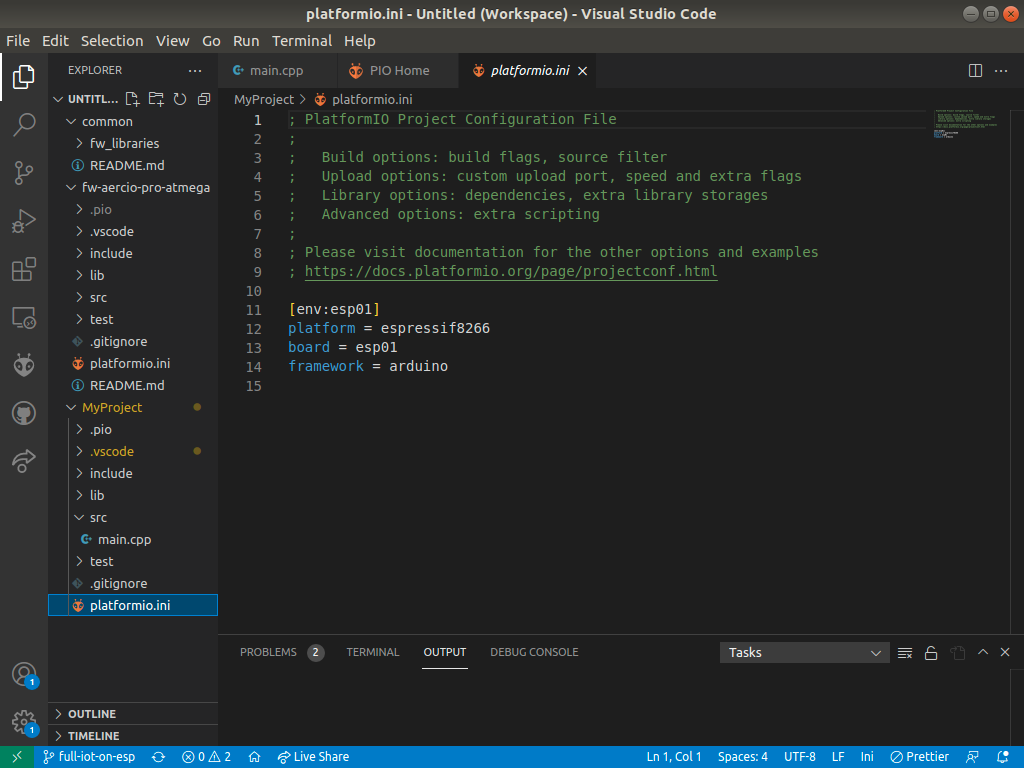
3. Finally you should have your project properly configured. Your main.cpp and platformio.ini files should look like Figures 3 and 4. They are automatically generated by the Wizard.
Uploading your code to the ESP
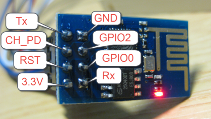
Before you upload your code into your ESP8266 microcontroller there are some aspects you must have in mind. The ESP266 has two boot modes: Flash and Normal, and the microcontroller enters into one of those modes depending on the voltage applied to pins GPIO0 and GPIO2, as described in Table 1. The Flash mode is used for programming the microcontroller, while Normal stands for normal operation. Figure 5 illustrates the ESP-01 board pinout.
Table 1. ESP8266 Programming modes
| Boot Mode | GPIO0 | GPIO2 |
| Flash | LOW | HIGH |
| Normal | HIGH | HIGH |
For uploading the code you must set up a circuit for flashing the ESP8266. You will need an FTDI 3.3v Board and USB to micro-USB cable as shown in Figure 6. The flashing circuit is shown in Figure 7. To enter the Flash mode, with the flash button pressed, click the reset button. This will reset the microcontroller into Flash mode. Then, upload your code from VSCode. Once the code has been uploaded you should enter the Normal mode by simply clicking the reset button. Table 2 shows the connection of the ESP-01 pins to the FTDI Board and the flashing circuit.
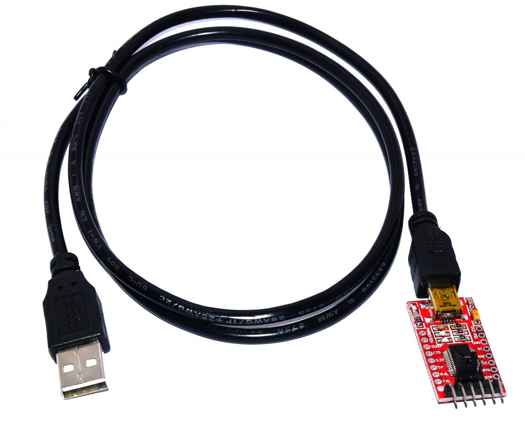
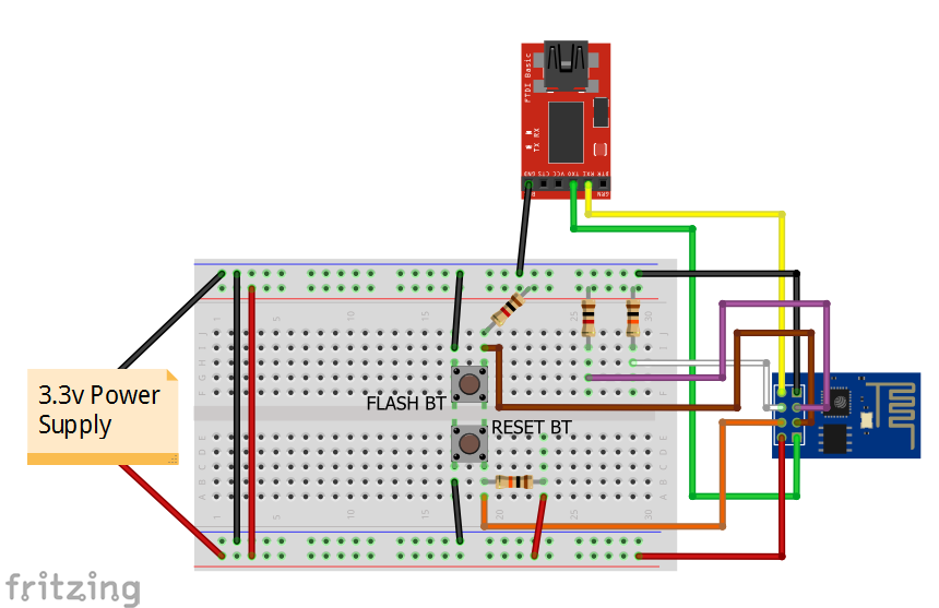
Table 2. ESP-01 connection to the flashing circuit and the FTDI Board
| ESP-01 | FTDI | Circuit connection |
| 3.3V | 3.3V | 3.3V |
| GND | GND | GND |
| TX | RX | — |
| RX | TX | — |
| GPIO0 | — | Connected to the output of the FLASH Button and a 1k pull-up resistor (the input of the FLASH Button connected to GND) |
| RST | — | Connected to the output of the RESET Button and a 10k pull-up resistor (the input of the RESET Button connected to GND) |
| GPIO2 | — | Connected to a 1k pull-up resistor (Always HIGH) |
| CH_PD | — | Connected to a 1k pull-up resistor |
Once you have your code uploaded you are all set for running, debugging, and deploying. Have fun!