
General Vision
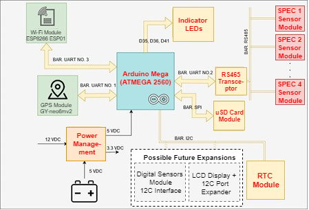
A general description of the monitor prototype was provided in The CLEAN Mobile Monitoring Prototype. The following guide provides a more detailed description of the deployment and interconnection of the hardware elements that composes the system, which can be observed in Figure 1.
The equipment measures pollutants from the Brazilian environmental legislation (REF: CONAMA No. 491/2018) which are: carbon monoxide (CO), nitrogen dioxide (NO2), sulfur dioxide (SO2), ozone (O3), and hydrogen sulfide (H2S).
The following diagram presents the interaction between the mobile monitor prototype components. All the mounting and connections between those components will be detailed in this manual.
The equipment
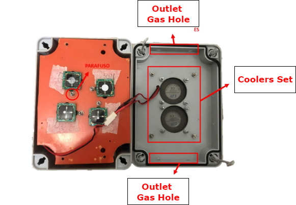
Figure 4 shows the internal components that will have their own installations and assembles covered in the following steps.
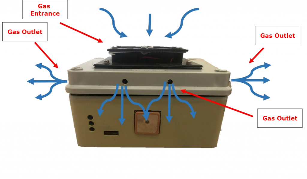
The gas flow inside the monitoring chamber is shown in Figure 3. There is a fixed barrier that separates the monitoring part from the Hardware components on the inside of the equipment. Both parts of the monitoring chamber are illustrated in Figure 4.
The Sensors
The mobile monitor prototype has a group of 4 SPEC Sensor sensors that contemplate de measuring: carbon monoxide (CO); nitrogen dioxide (NO2); sulfur dioxide (SO2) and ozone (O3)
Components and Controllers
The monitoring, storage, and data sending operator are based on the Arduino Mega 2560 platform, which uses a microcontroller Microchip’s ATMega2560. To operate successfully, the system includes: Wi-Fi module, SD card Module, GPS Module, and operational LED indicators.
Equipment assembly
The mounting has several commercial components, and it needs a leisure cut service in acrylic sheet, handwork on a few measuring pieces, cuts, and holes. This page has a chronological work method suggestion which details each of those specific needs, making it easier to organize and less complex to work on.
The equipment mounting seems a bit complex at first look, however, the researchers involved in the projects had strategically developed it with components accessible in literature and market, with the best cost-benefit possible.
The development team continues working to adapt the project to an even more accessible and efficient version. Future improvements are still been developed to reduce the double work and artisanal operations.
Monitoring chamber
The first assemble step is to prepare the monitoring chamber and after that add the other parts of the system.
The materials and components list necessary to assemble the reception and exhaust of gas from the sensor’s chamber or monitoring box is demonstrated in Table 1.
| Qnt | Item | Description | Characteristics | Ilustrative Picture |
| 2 | Cooler | Induced air intake | 5V 40x40mm Cooler |  |
| 8 | Screw | Fixing cooler | M2x15mm Flat head screw |  |
| 8 | Nuts and Washer | M2x30mm Nut and Washer for the Screws | 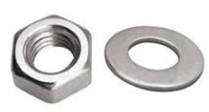 | |
| 1 | Junction Box | 154x110x70mm Kraus Muller |  |
Table 1. Components and materials list for mounting the reception and exhaust gases from the sensor chamber.
The monitoring chamber behaves all the sensors, forced ventilation system, voltage regulator source, communication modules, and storage.
In Figures 6 and 7 can be seen the chamber with the constructive and location details of the components. All the components are fixed by M2*10+4 spacers directed fixed on the plastic sheet on the equipment box.
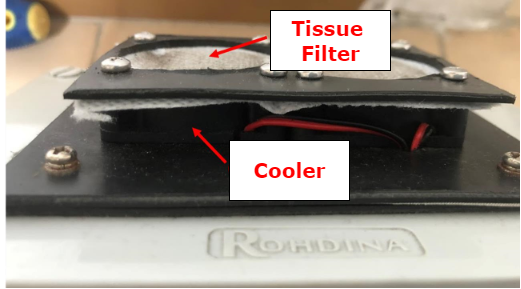
The 12V 40X40MM coolers are installed at the superior equipment cover, screwed with M2X15mm screws with internal nut. Two sheet plastic was cut to install a tissue that acts as a particulate material filter, as is shown in Figure 5.
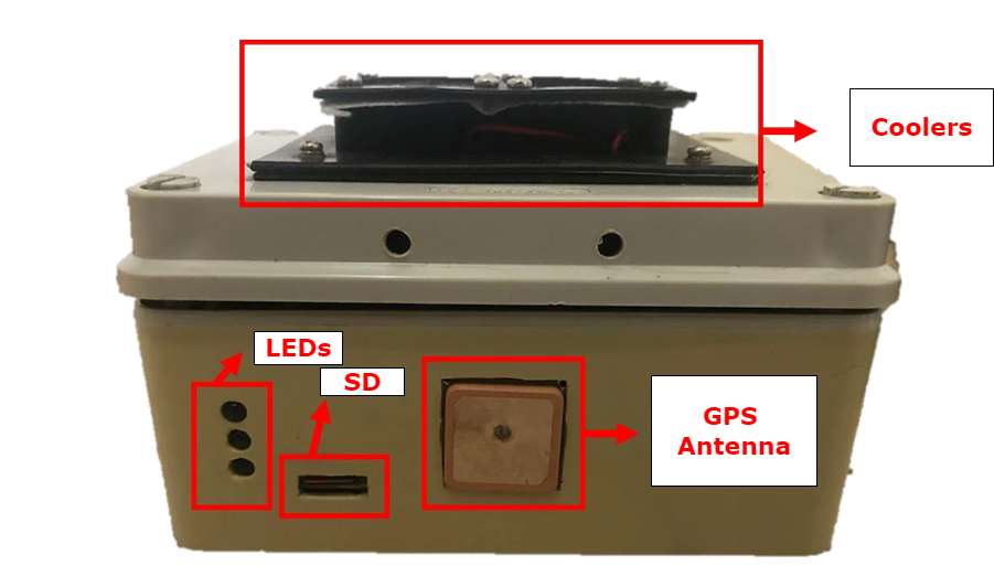
Figure 7 respective legends for the Hardware components:
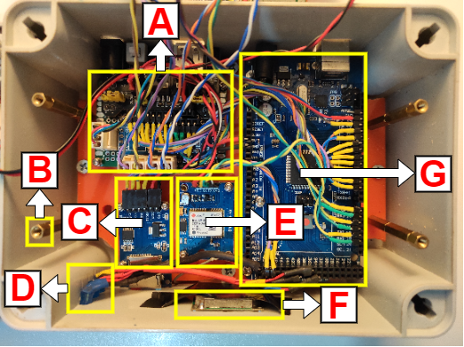
A) Voltage regulator source”;
B) Set of spacers to hold the sensor array;
C) SD module;
D) Indicator LEDs;
E) GPS module;
F) GPS antenna;
G) Arduino MEGA.
Sensors Arrangement
The group of 4 SPEC Sensor sensors will have their installation detailed below in Table 2.
| Qnt | Item | Description | Characteristics | Illustrative Image |
| 1 | SPEC Sensors: DGS-O3- 968-042_9- 6-17 | O3 Sensor |  | |
| 1 | SPEC Sensors: DGS-SO2- 968-038 | SO2 Sensor |  | |
| 1 | Spec Sensors: DGS-NO2- 968-043_96-17 | NO2 Sensor |  | |
| 1 | Spec Sensors: DGS-CO- 968-034 | CO Sensor |  | |
| 5 | RS485 | Converter Module RS485 to Arduino |  | |
| 8 | Spacers | M2*10+4 Spacers to PCB Tinned Universal Breadboard | With Screws |  |
| 6 | MOLEX Connector | MOLEX Connector 4 pins |  | |
| 9 | MOLEX Connector | MOLEX Connector 2 pins |  | |
| 5 | PCB Tinned Universal Breadboard | 2x8cm | Board to fix MAX485 and SPEC Sensor’s Sensors |  |
| 1 | Plastic box | Junction Box | 154x110x70mm |  |
Table 2. List of components for assembling the SPEC Sensor’s sensor array.
Fixing the arrangement sensors to the monitoring chamber

A plastic sheet is needed to fix the sensors correctly and also create efficient isolation between the gas chamber and hardware spot, it is shown in Figure 8.
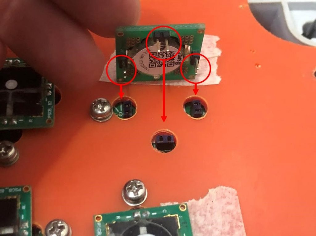
Also in Figure 8 is demonstrated the sensor’s fixation on the plastic sheet with 2.5X5mm screw and nut, directly put on the sensors sheet.
Fixing the SPEC Sensor’s sensor arrangement
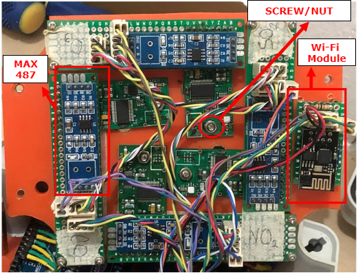
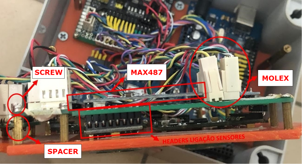
The SPEC sensors array fixing is made through manually made PCB Tinned Universal Breadboard which has female kind headers where the sensors are connected. The MAX487 transceivers are also installed at this PCB Tinned Universal Breadboard . The PCB Tinned Universal Breadboard is fixed at the plastic sheet which was made to the sensor’s module through the M2*10+4 spacers. The electric and data connection between the PCB Tinned Universal Breadboard is made by MOLEX connectors.
The connection details from SPEC Sensor’s sensor with the dedicated plate are shown in Figure 9; the sensor’s array bottom view is presented in Figure 10 with the 2,5X5mm screws fixation details. Figure 11 shows a PCB Tinned Universal Breadboard side view, as well the spacers fixation, headers, MAX487, and the MOLEX connectors used.
The spacers go directly through the sensor’s plastic sheet. To fix them is necessary to make a 2mm hole and thread the spacers into it.
SPEC Sensor’s Sensor connections
To continue the prototype assemble is necessary to fix the sensor’s array with the internal hardware components from the measuring chamber, making the communication electrical connection and sensor’s array power supply.
The connections can be made with 0.2mm² section thread, soldering headers at the tip, isolating them with head shrink duct. Figure 12 shows a complete diagram of the SPEC sensor’s sensor arrangement, presenting the communication and power supply information,

Sensor’s Chamber Power Supply and Communication Connections
The sensor’s chamber hardware components are listed below in Table 3.
| Qnt | Item | Description | Characteristics | Illustrative Image |
| 1 | PCB Tinned Universal Breadboard | 2x8cm | Board to install the voltage regulator source | 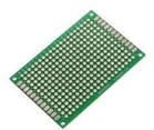 |
| 1 | Module GPS NEO-6M GPS | GPS Module with antenna |  | |
| 1 | ESP8266 ESP-01 | Wi-Fi Serial Module |  | |
| 1 | Mb102 | 3V and 5V Regulator Source |  | |
| 16 | Spacers | M2*10+4 Spacers for PCB Tinned Universal Breadboard with screws | Used to fix the components of the circuit |  |
| 1 | SD Module | 43MD36 Type |  |
Table 3. List of components for assembling the sensor chamber.
After assembling the sensor’s array and prefixing the measuring chamber electronic components, it will be necessary to make the power source’s electrical and communication connection of all the involved components in the process. To do that, it is used 0.2mm² section thread or superior for communication and 0.5 mm² for power supply connections.
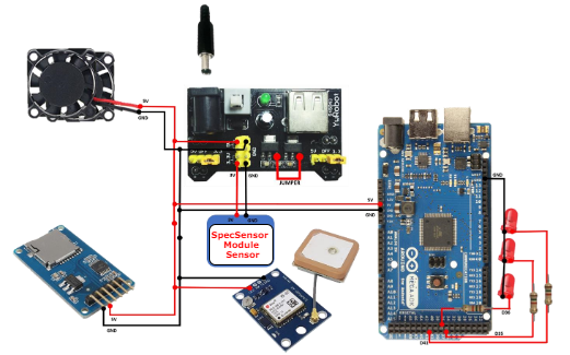
Figure 13 is shown the power supply diagram. To improve the performance of the regulatory source it was used a jumper and it is demonstrated in the same diagram.
The components fixation is made by metal spacers, which is shown in Figure 11, to do that it is made a 2 mm hole in the plastic and screw the spacers into this hole.
The communication connections diagram is shown in Figure 14.
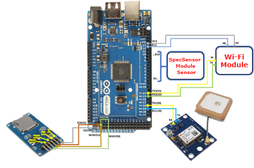
The Wi-Fi’s communication and power supply is shown in Figure 15, which is installed ate the sensor’s plastic sheet as it is shown in Figure 10.

