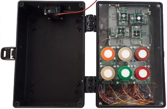
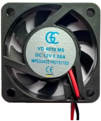
The low-cost fixed monitor was developed at the Laboratory of Air Quality Control (LCQAr) for measuring air pollutants: carbon monoxide, nitrogen dioxide, sulfur dioxide, ozone, and hydrogen sulfide. Figure 1 shows the main block of the system: the sensing block. It is composed of three subblocks: 1) sensing chamber, 2) sensors, and 3) microcontroller, as shown in Figure 2. The sensing chamber captures ambient air samples into the sensors. For this prototype, we used two 12 VDC cooler fans as shown in Figure 3. For more details on developing the gas sampling block check out The Gas Sampling Development Guide. The sensors we used were four digital electrochemical sensors for IoT manufactured by SPEC Sensors, and six electrochemical B4-series sensors manufactured by Alphasense as will be described below.
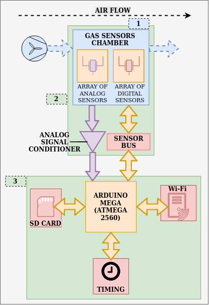
As the microcontroller, we selected a Microchip ATMega2560, embedded into an Arduino Mega platform. The ATMega2560 receives the concentration readings from the digital sensors through a serial hardware interface and acquires the analog signals from the Alphasense sensors through the microcontroller’s analog inputs. The hardware stores the gas concentration information, alongside a timestamp (obtained from a Real-Time Clock) when the readings were taken, into a micro SD card and transmits it to a remote server. Since the monitor will be installed at a fixed location a GPS module is not strictly necessary. A Wi-Fi connection is required for data transmission which is established through an ESP8266 module.
The Sensors
The sensors block consists of an array of ten electrochemical gas sensors and their conditioning circuits. For more detailed information on the electrochemical principle for measuring gas concentration check out the review by Ronan Baron and John Saffell on the subject (BARON and SAFFELL, 2017). The sensors used for this prototype were four digital screen-printed electrochemical sensors for IoT manufactured by SPEC Sensors, and six electrochemical B4-series sensors manufactured by Alphasense as shown in Table 1.
Table 1. Sensors features
| Qty. | Model | Manufacturer | Air pollutant | Range | Resolution | Supply voltage (*) | |
| 1 | DGS-O3 968-042 | SPEC Sensors | Ozone | 0 – 5 ppm | 20 ppb | 3.3 V | 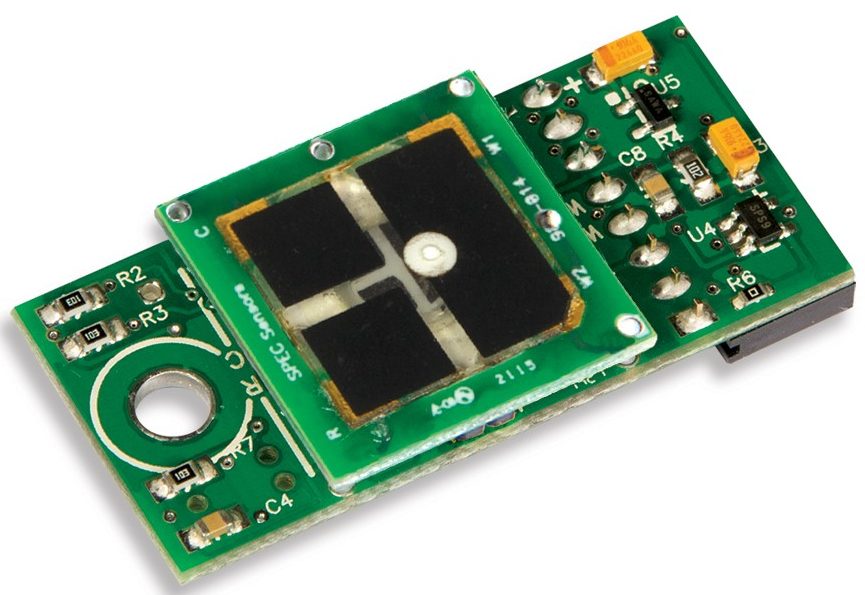 |
| 1 | DGS-NO2 968-043 | SPEC Sensors | Nitrogen dioxide | 0 – 5 ppm | 20 ppb | 3.3 V | |
| 1 | DGS-SO2 968-038 | SPEC Sensors | Sulfur dioxide | 0 – 20 ppm | 50 ppb | 3.3 V | |
| 1 | DGS-CO 968-034 | SPEC Sensors | Carbon monoxide | 0 – 1000 ppm | 100 ppb | 3.3 V |  |
| 1 | CO-B4 | Alphasense | Carbon monoxide | 0 – 1000 ppm | 4 ppb | 3.5 – 6.4 V |  |
| 1 | NO2-B43F | Alphasense | Nitrogen dioxide | 0 – 20 ppm | 15 ppb | 3.5 – 6.4 V |  |
| 1 | SO2-B4 | Alphasense | Sulfur dioxide | 0 – 100 ppm | 5 ppb | 3.5 – 6.4 V |  |
| 2 | OX-B431 | Alphasense | Ozone | 0 – 20 ppm | 15 ppb | 3.5 – 6.4 V |  |
| 1 | H2S-B4 | Alphasense | Hydrogen sulfide | 0 – 100 ppm | 1 ppb | 3.5 – 6.4 V |  |
*Note: This is the voltage for powering the interface circuit boards of the sensors. See the Sensors Conditioning section
SPEC Sensors
The SPEC sensors are amperometric, i.e. electrochemical sensors that generate a current proportional to the gas concentration (STETTER and LI, 2008). They use a three electrodes electrochemical configuration, which is the most common for this kind of transducer, i.e.: working, reference, and counter electrodes. SPEC stands for Screen-Printed Electrochemical, which is the technology used for manufacturing the sensors, reducing their cost and dimensions, and still maintaining a high performance (SPEC Sensors, 2016).
Alphasense Sensors
Alphasense manufactures amperometric electrochemical sensors. Specifically, the B4 series sensors use a fourth electrode, called the auxiliary electrode, which compensates for the effects of the temperature and the relative humidity on the outputs of the sensors (BARON and SAFFELL, 2017). For more information about the effects of environmental variables on the responses of the sensors check out the application note AAN 110 by Alphasense. For additional information on the B4 series sensors from Alphasense, like electrical specifications, dimensions and pinout, please refer to the sensors’ datasheets in Table 1.
Sensors Conditioning
Amperometric electrochemical sensors produce an output current that is proportional to the gas concentration. To read this electrical signal from an acquisition system, the output current must be transformed into a voltage signal. For that purpose, the most commonly used circuit is the potentiostat. Alphasense and SPEC both provide potentiostat circuit boards for easily coupling their sensors into a monitoring system.
SPEC Sensors Conditioning Interface
The digital sensors for IoT that are provided by SPEC are composed of an electrochemical transducer mounted on a circuit board with a potentiostat circuit, for converting the sensor output (current) into voltage; an embedded microcontroller; and a temperature and relative humidity sensor. The microcontroller converts the voltage signal into gas concentration values and implements a software compensation for the effects of the temperature and the relative humidity on the sensor output. The concentration, temperature, and relative humidity values are transmitted through a UART interface following a serial protocol defined by the manufacturer. This conditioning board acts as an abstraction layer for signal conditioning that allows easy integration of the sensors to any monitoring system. For more information on the SPEC sensors, like electrical specifications, dimensions, pinout, and serial protocol please check the sensors’ datasheets (Table 1) and the Digital Gas Sensor Developer Kit.
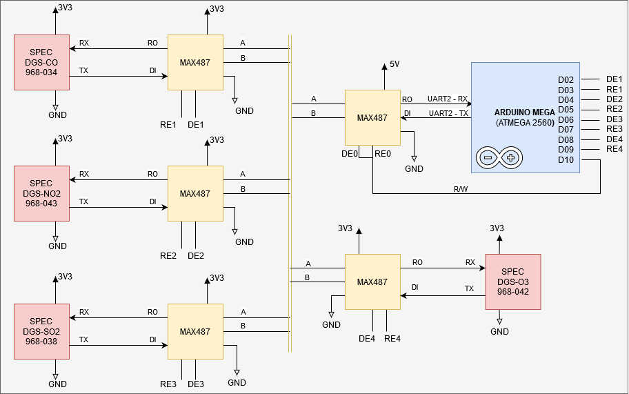
For our prototype, we coupled the sensors shown in Table 1 from SPEC, mounted on their interfacing boards, and the Arduino MEGA microcontroller into an RS-485 bus. For each sensor and the microcontroller, a MAX487 transceptor was used for interfacing between the UART ports and the RS-485 bus. Figure 4 illustrates the connection between the sensors and the Arduino MEGA. The serial port used for that purpose on the microcontroller was UART2. The digital ports D02 – D10 of the Arduino were used as outputs for controlling the Read/Write sequence from and to the sensors over the RS-485 bus. The sensor boards must be powered with a 3.3 V power supply. For more details on mounting and connecting the SPEC sensors check out The SPEC Sensors Mounting Guide.
Alphasense Sensors Conditioning Interface
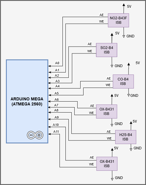
Alphasense provides Individual Sensor Boards for their B4 series 4-electrode gas sensors. Those boards incorporate equivalent potentiostat circuits for both the working and the auxiliary electrodes. The outputs from each potentiostat channel were connected to the analog inputs of the Arduino MEGA microcontroller, as shown in Figure 5. AE and WE represent the signals corresponding to the auxiliary and working electrode respectively. Six sensors were used in our prototype which twelve analog inputs of the microcontroller (A0 – A11). Each ISB was powered with 5 V. For more details on mounting and connecting the Alphasense sensors check out The Alphasense Sensors Mounting Guide.
The Microcontroller
The Arduino MEGA 2560 microcontroller coordinates the tasks associated with data acquisition, data storage, timing, geolocation, and communication. The firmware for this prototype is available in our firmware repository. For details on the firmware structure and firmware libraries please refer to the Firmware Documentation.
Data Storage
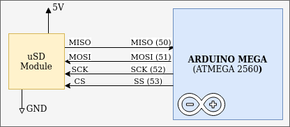
For data storage, we used a micro SD module connected to the microcontroller through a Serial Peripheral Interface (SPI). The micro SD card works with 3.3 V, but the module includes buffers and a voltage regulator that allows a direct connection to the Arduino SPI and a 5 V power supply, as shown in Figure 6.
Real-Time Clock
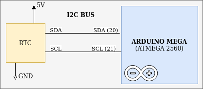
We used the Real-Time Clock (RTC) DS1307 module for keeping track of the date and time continuously. This module is a low power clock/calendar that provides seconds, minutes, hours, day, date, month, and year information. The end of the month date is automatically adjusted for months with fewer than 31 days, including corrections for leap year. The DS1307 has a built-in power sense circuit that detects power failures and automatically switches to the backup supply through a battery. Timekeeping operation continues while the part operates in low-power mode from the backup supply. The module connects to the Arduino MEGA through the I2C interface and is powered with 5 V, as shown in Figure 7.
Wi-Fi Communication
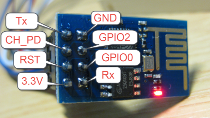
For Wi-Fi communication, we used the ESP-01 module (Figure 8). This module incorporates the ESP8266 microcontroller together with an embedded antenna with a power gain of 3dBi and a range of up to 90 m. The ESP8266 is a System on Chip (SoC), manufactured by Espressif Systems, which integrates the 32-bits microprocessor Tensilica L106 and implements the TCP/IP and 802.11 b/g/n WLAN MAC protocols. The ESP-01 also incorporates a 512 kB flash memory for programming, which is accessible to the ESP8266 via SPI. It also has eight pins that are used for power supply, connection to the ESP8266 serial port, and connection to four GPIOs of the ESP8266, as shown in Figure 8. For more details on the ESP-01 pinout and how to program and connect this module to the Arduino MEGA, please refer to The ESP-01 Module Programming Guide. A description of the firmware we developed for the ESP8266 microcontroller can be found in The ESP8266 Firmware.
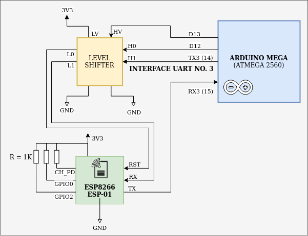
The ESP-01 module provides the connection to a Wi-Fi network for the Arduino MEGA. As shown in Figure 9, a level shifter circuit is required for interfacing with the Arduino pins as a result of the different operating voltages of the boards. The communication between the ATMega2560 and the ESP8266 microcontrollers is implemented over a UART interface (UART3 on the Arduino board), following a communication protocol that is described in detail in The ESP-01 Module Programming Guide. The Arduino acts as a master over the ESP8266, whose only initiative is to establish a connection to the Internet. Once the connection is set, the Arduino can send commands for creating HTTP posts, getting the internet time, or getting the Google geolocation coordinates; for more details please refer to The ESP-01 Module Programming Guide). The Arduino microcontroller can also reset the ESP8266 through the D12 GPIO pin.
References:
- BARON, R.; SAFFELL, J. Amperometric Gas Sensors as a Low-Cost Emerging Technology Platform for Air Quality Monitoring Applications: A Review. ACS Sensors, v. 2, n. 11, p. 1553–1566, 11 2017. ISSN 2379-3694. Available at: <https://pubs.acs.org/doi/10.1021/acssensors.7b00620>
- SPEC Sensors. SPEC Sensor Operation Overview SPEC Sensor TM Operation and Performance Considerations. [S.l.], 2016. 1 – 6 p. Available at: <http://www.spec-sensors.com/wp-content/uploads/2016/05/SPEC-Sensor-Operation-Overview.pdf>
- STETTER, J. R.; LI, J. Amperometric Gas Sensors A Review. Chemical Reviews, v. 108, n. 2, p. 352–366, 1 2008. Available at: <https://pubs.acs.org/doi/10.1021/cr0681039>